
Warm Tip: If you want to know more details about our construction services, materials, or project solutions, please contact us for a free consultation.
Systematic analysis of surface shrinkage depression defects in QT450-10 wheel hub castings produced by the coated sand process
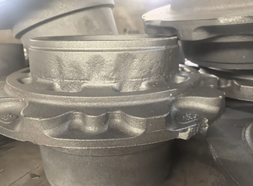
The product is a trailer ductile iron wheel hub, material QT450-10, produced by the coated sand shell mold process. Surface shrinkage depression (shrinkage cavity/sink) defects appear in the flange area of the casting.
On-site composition testing: base iron liquid carbon 3.8%, base silicon 1.5%, and after nodularization and inoculation the final silicon is 2.6%. A systematic analysis is carried out across the entire chain — composition, graphitization expansion mechanism, coated sand shell mold characteristics, feeding system, pouring process, and nodularization/inoculation — to clarify the underlying logic of shrinkage depression formation and provide a supporting corrective action plan.
First, let’s calculate from composition and carbon equivalent. Base iron liquid C=3.8%, final Si=2.6%. Roughly calculating carbon equivalent CE=C+Si/3, CE≈4.67%. The conventional safe carbon equivalent range for QT450-10 is 4.30%–4.50%. The current carbon equivalent is clearly on the high side, which is one of the most core source factors for this shrinkage depression.
The coated sand process is fundamentally different from clay sand and resin sand. The coated sand shell mold has extremely high rigidity and extremely low yielding capacity. Many process engineers form an inertial understanding that shell molds are not afraid of graphite expansion, so they actively raise the carbon equivalent and rely on graphitization expansion to achieve self-feeding. However, this approach has boundary conditions.
Carbon 3.8% belongs to the high-carbon level. High carbon brings two changes: first, the total amount of precipitated graphite greatly increases, and the graphitization expansion amount is larger; second, the eutectic solidification interval widens. The solidification of ductile iron is different from gray iron — it is mushy solidification, not layer-by-layer solidification. After molten iron enters the coated sand shell mold, in the early stage of eutectic transformation, a large amount of graphite rapidly precipitates and expands in volume. The highly rigid coated sand shell mold hardly yields, and the expansion pressure squeezes the casting body inward. In the middle and late stages of solidification, graphite precipitation is basically complete, and the austenite matrix undergoes solid-state shrinkage. The compensation capacity of the early expansion is exhausted, and the thick and heavy hot spot positions have no continuous supply of external molten iron, so the surface sinks inward, forming visible surface shrinkage depression.
At the same time, let’s look at the change in silicon: base iron liquid silicon 1.5%, and after nodularization and inoculation the final silicon is raised to 2.6%. Silicon is a strongly graphitization-promoting element. The higher the silicon content, the higher the graphite precipitation temperature and the greater the precipitation amount. The base iron liquid silicon is very low, and the molten iron supercooling is on the high side. After nodularization and inoculation, silicon is suddenly raised, and graphite precipitates explosively concentrated in the early eutectic stage, causing severe imbalance in the expansion timing. Excessive early expansion and no compensation for later shrinkage exactly correspond to the typical shrinkage depression characteristic of “expand first, shrink later.” Many workshops only focus on whether the final silicon is within the material standard range and ignore the graphite precipitation rhythm problem caused by low base iron liquid silicon and too large an inoculation silicon increase. QT450-10 requires elongation, and many practitioners are accustomed to increasing final silicon to ensure the number of graphite nodules and improve toughness. However, on a high-rigidity mold like the coated sand shell mold, final silicon 2.6% combined with carbon 3.8% directly exceeds the carbon equivalent, very easily triggering surface shrinkage depression.
Second, the process characteristics of the coated sand shell mold itself amplify the defects caused by composition imbalance. After curing, the coated sand shell mold has high strength, high rigidity, and almost no yielding capacity — this is a double-edged sword. The advantage is that it can suppress mold wall movement and flashing, and is suitable for wheel hub castings with high dimensional accuracy requirements; the shortcoming is that it cannot absorb part of the expansion stress through mold yielding like clay sand. When the carbon equivalent is on the high side and graphite expands in a concentrated manner, the shell mold does not deform outward, and the expansion stress acts entirely inside the casting. The casting shell first forms a thin hard skin, and the internal mushy solidification zone continues to shrink. There is no space to release stress outward, so it can only collapse inward, forming a smooth-surfaced shrinkage depression pit.
In addition, there is another easily overlooked point about the coated sand shell mold: uneven shell wall thickness. The wheel hub flange position has a large hot spot. If the corresponding shell layer is on the thin side, the shell mold locally overheats after pouring, the coated sand resin is overburned, the shell layer strength decreases, and local micro-yielding occurs. Local yielding causes the casting surface layer to first bulge slightly outward. When the matrix shrinks, the mold cavity space has already become larger, and the molten iron cannot fill the shrinkage space, ultimately appearing as shrinkage depression. Also, unreasonable shell mold closing gaps and shell core venting design will aggravate this phenomenon: poor venting raises the mold cavity back pressure, and the feeding channel solidifies prematurely in the late filling stage, so the hot spot receives no feeding.
Third, the matching problem between the feeding system and the casting structure hot spot. The trailer wheel hub flange is a continuous thick and heavy hot spot, and the R-angle transition between the flange and the barrel concentrates heat, making it a high-risk position in the coated sand process. The riser design of coated sand shell molds has limitations; most risers on shell molds are blind risers formed with the shell, and the riser volume and modulus are not easy to make large. If the riser modulus does not match the flange hot spot modulus and the riser neck size is on the small side, the riser will solidify prematurely and the feeding channel will be sealed off.
In many wheel hub coated sand processes, the ingate is set at the barrel body position, far from the flange hot spot. After filling is completed, the flange position enters the solidification stage first, and the riser does not have enough high-temperature molten iron for continuous supply. The mushy solidification characteristic of ductile iron determines that pure reliance on graphite self-feeding has a limit. When the carbon equivalent is appropriate, self-feeding takes effect; when the carbon equivalent is excessive, the expansion timing is disordered, self-feeding fails, and shrinkage is directly exposed on the casting surface. Some processes do not place external chills at the flange hot spot position, and the continuous thick and heavy section has too long a solidification time and a long shrinkage duration, further amplifying the shrinkage depression risk.
Fourth, the influence of nodularization and inoculation treatment methods. The base iron liquid silicon is only 1.5%, and all silicon increase relies on inoculant, belonging to large-increment inoculation. Adding a large amount of inoculant at one time causes instantaneous inoculation excess, graphite precipitates in large amounts in a short time, graphite nodules cluster, and local expansion concentrates. If in-ladle inoculation is used without stream inoculation as a supplement, graphite distribution is uneven, graphite precipitation concentrates in the hot spot area, and the expansion peak occurs earlier. At the same time, for high-carbon molten iron with 3.8% carbon, the difficulty of controlling nodularizer absorption rate increases. Once the nodularization rate fluctuates and graphite nodule sizes are uneven, some areas have less graphite and insufficient expansion, and shrinkage appears. There is also the risk of nodularization decay. The coated sand shell mold dissipates heat slowly, the casting solidification cycle is longer, and the molten iron residence time is long. After nodularization decay, the amount of graphite decreases, the self-feeding capacity weakens, and shrinkage depression is likewise induced.
Fifth, the superimposed influence of pouring temperature, pouring rhythm, and cooling control. The coated sand shell mold dissipates heat slowly. Compared with green sand, the casting cooling cycle is longer. If the pouring temperature is on the high side, the solidification time is prolonged, the matrix shrinkage increases, and the hot spot effect is further amplified. Even if the carbon equivalent is only slightly excessive, high-temperature pouring will amplify the shrinkage depression defect. The coated sand shell mold is a thin-walled shell. If the filling speed is too fast, air entrainment easily occurs; if filling is too slow, the flange position forms a skin prematurely and the feeding channel closes early. At the same time, after shell mold pouring, many workshops shake out the shell early to improve turnover. The casting leaves the mold before completing solidification shrinkage, loses external constraint, and the surface layer collapses, forming shrinkage depression.
It is also necessary to distinguish coated sand process shrinkage depression from other defects. The shrinkage depression surface is smooth, without porosity or slag inclusions. After sectioning, the area below the depression is definitely accompanied by internal porosity; unlike mold wall movement, which is overall outward bulging, shrinkage depression is local sinking; and it is clearly different in appearance from cold shuts and flow marks. Many workshops treat shrinkage depression as porosity or slag holes and repeatedly adjust venting and slag removal, but the defect does not improve after repeated adjustments. The root cause is that they have not grasped the core of excessive carbon equivalent and imbalanced expansion timing.
Based on the composition of this heat, a targeted corrective action plan is given. First, reduce the carbon content of the base iron liquid, control carbon in the 3.50–3.65% range, maintain final silicon at 2.40–2.50%, and press the carbon equivalent down to the reasonable range of 4.35–4.45% to avoid concentrated explosive graphite expansion. The current situation of low base iron liquid silicon of 1.5% can be retained, but reduce the single inoculation silicon increase amplitude and switch to stream inoculation to refine graphite and smooth the graphite precipitation rhythm, avoiding an early expansion peak. Second, optimize the coated sand shell mold, ensure uniform shell layer thickness corresponding to the flange, full curing, and eliminate local resin overburning strength reduction; reasonably open venting grooves to reduce mold cavity back pressure. Third, optimize the feeding system, calculate the flange hot spot modulus, enlarge the riser neck, ensure the riser solidifies later than the casting hot spot, and add external chills at the flange hot spot position to break up the continuous hot spot and shorten solidification time. Fourth, optimize the nodularization and inoculation combination, reduce in-ladle inoculation, pair with stream inoculation, ensure fine and uniform graphite nodules, stabilize the nodularization rate, and avoid local concentrated graphite precipitation. Fifth, control the pouring temperature. For coated sand QT450-10 wheel hubs, control the pouring temperature at 1360–1390°C; high-temperature pouring is prohibited; after pouring, ensure sufficient in-flask cooling time, and strictly prohibit early shell knocking and shakeout.
In summary, the primary cause of surface shrinkage depression in this coated sand QT450-10 wheel hub is the excessive carbon equivalent caused by carbon 3.8% combined with final silicon 2.6%, which causes imbalanced graphitization expansion timing; the high-rigidity characteristic of the coated sand shell mold amplifies the expansion-shrinkage contradiction; superimposed with insufficient hot spot feeding, uneven graphite precipitation caused by large-increment inoculation, and inadequate cooling control and other multiple factors, surface shrinkage depression ultimately forms at the flange hot spot position. The coated sand process cannot copy the high-carbon-equivalent production approach of clay sand. Under rigid molds, the carbon equivalent window is narrower, and graphite expansion and matrix shrinkage must be balanced to stably eliminate this type of shrinkage depression defect.